|
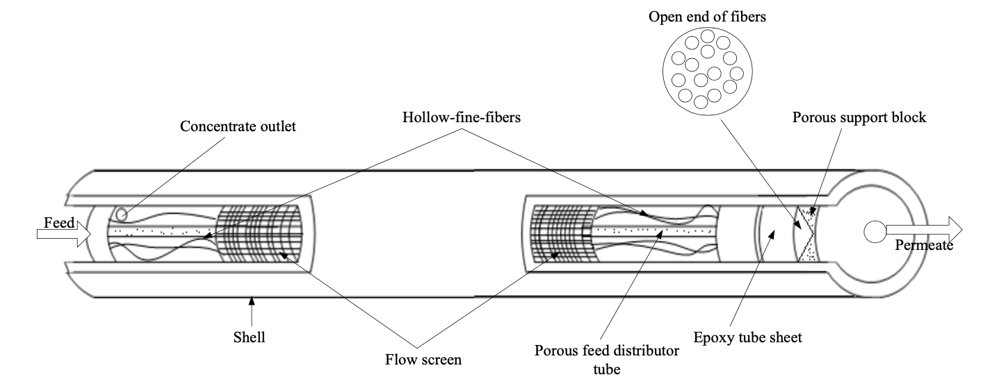
Introduction Hollow-fibre membranes are of high commercial importance. Their fabrication by spinning dopes or mixtures containing membrane forming materials (polymers) has been described in a series of patents by Mahon (1966), assigned to the Dow Chemical Company [1,2]. Hollow-fibre membranes were developed to be used for a wide range of applications, such as water purification (e.g., potable water production from saline or non-saline resources, bioseparation, waste water treatment), gas separation and membrane contactors [3-5]. The diameters of hollow fibres vary over a broad range, from 50 to 3000 μm. Hollow fibres can either made as a homogenous dense structure or, more preferably, an asymmetric microporous structure. Hollow-fine-fibre RO membranes operate at high pressures and this is accomplished by engineering the membrane material into special modules. Essentially, a hollow-fine-fibre membranes module consists of thousands or millions of individual fine fibres, depending on fibre dimensions, which are then are looped into a bundle around a perforated central feed tube. Both ends of the fibre bundle are sealed off by a potting resin creating a tube-sheet, open on one end and closed on the other end (Figure 1).
Hollow fibres have key advantages over other membrane configurations, such as flat-sheets. Hollow fibres have extremely high membrane surface area to pressure-vessel volume, which gives high productivity per unit volume. It is for this reason that hollow fibres are commonly used in industry [6]. The other advantage of the hollow fibres is that they are self-supporting, unlike the flat-sheet membranes that need a supporting material. In addition, concentration polarization usually is smaller under most practical conditions in hollow fibres than in flat-sheet membrane systems [7]. It is well known that it is very difficult to develop a hollow-fibre spinning process by adopting the process conditions developed for asymmetric flat-sheet membranes. This is because there are two coagulation processes occurring during the spinning of hollow fibre (the interior and exterior surfaces), while there is only one coagulation process on the surface for an asymmetric flat-sheet membrane. The spinning of asymmetric hollow-fibre membranes requires special handling procedures in order to achieve and maintain optimum permeation properties [8], particularly in the following steps in the fabrication process:
The objectives of this study are the following:
To perform collapse pressure tests on produced fibres to validate the calculated fibre dimensions data. Collapse and Pressure Drop Calculations In order for hollow-fine-fibre membrane to be useful in RO pressure applications, it must be able to withstand a considerable trans-membrane pressure difference. The ability of brackish water hollow-fine-fibre membranes to withstand its operating pressures without collapse, will be taken into account as an issue; firstly, to produce highly resistant hollow-fine-fibre diameters by using a suitable spinneret, and secondly, to provide a membrane module with high packing density (the smaller fibre dimensions, the higher resistance to brackish water operating pressures and subsequently the higher packing density). To determine the acceptable fibre dimension for RO, it was necessary to adopt the buckling pressure equation of cylindrical shells under external pressures to equate fibre dimensions to collapse pressure. Note that the smaller the fibre dimensions are, the higher pressure drop across the membrane, thus calculating the pressure drop across the fibre bore must also be taken into account to determine the acceptable fibre dimensions [9]. Elastic Collapse Pressure on Cylindrical Shells Subjected to External Pressure Elastic collapsing pressure is the maximum pressure that can be applied to hollow cylindrical tubes for wall deformation to remain reversible. At higher pressures, the tubes collapse. When the external pressure applied on a cylindrical shell or tube exceeds certain values, the tube collapses, with longitudinal corrugations, according to the pressure increase [10]. This problem of finding the pressure required to bring about this collapse depends for its solution upon what is known in mathematical elasticity as the general theory of cylindrical shells under external pressure. For this reason, more rigid mathematical theory, which has been adopted by Southwell [10], showed a good agreement with the theory of collapse pressure of bore tubes. This theory of elastic collapsing pressure will be used in this study and its formula is expressed by the following equation (1):
where P is the collapse pressure, E is Young’s modulus (GPa), v is the Poisson’s ratio (dimensionless), OD is the outside diameter (μm), and t is thickness of the hollow fibre (μm) (outside radius - inside radius). The equation suggests that collapse pressure of hollow fibre is very high because OD is very small. Pressure Drop Across the Wall of a Hollow-fine-fibre Membranes There is ample evidence in the literature suggesting that the pressure drop along the fibre bore varies considerably with the fibre diameter, the smaller the diameter, the higher the pressure drop [11]. It is therefore necessary to calculate the effect of pressure drop in the fibre bore and how much of this variation in the pressure drop will affect the chosen fibre dimensions determined by collapse pressure calculations. In this study, the steady laminar flow of incompressible fluid through the hollow-fine-fibre with a semi-permeable wall and length will be expressed by the Hagen-Poiseuille equation for laminar flow [12], in order to calculate the pressure drop across the fibre bore. Pressure Drop Across the Fibre Wall of the Hollow-fine-fibre Membranes Hermans [13,14] studied the effect of hydraulic flow characteristics of Berman’s analysis in a permeable wall of a tubes on the flow mechanism of a hollow fibre and suggested that a Poiseulle’s equation can be applied to the flow pattern inside the fibres. He therefore combined that equation with a membrane transport equation of pure water and proposed an initial model for complete water retention by hollow-fibre RO membranes. This model was taken as a basis by Orofino [15] in the development of the hollow filament technology for a RO desalination system. The axial flow on the inside of a single hollow fibre was studied by Chen and Petty [16]. They studied the volumetric flow of an incompressible fluid undergoing RO in a hollow fibre with a semipermeable wall by applying Darcy’s law for membrane transport. The fibre was sealed at one end with epoxy and open at the other end to atmospheric pressure. They used a diffusion model to describe the passage of salt through the membrane. However, Evanglista and Jonsson [17] proposed a model were the pressure drop inside a hollow fibre was considered with the concentration polarization on the shell side. Sekino [18] used the Kimura-Sourirajan model to propose a friction-concentration-polarization model by employing the solution diffusion model and concentration polarization, and calculating the pressure drop in the hollow fibre bore using the Poiseuille equation and the pressure drop on the shell side by the Ergun equation. Ohya et al. [19] studied the RO characteristics of a B-9 hollow-fibre membrane by neglecting the pressure drop on both the shell side and in the fibre bore. They took into account the effect of concentration polarization on the bulk side. Other assumptions, including neglecting the osmotic pressure and the concentration polarization on the bulk side of the membranes, where made by Starov et al. [20] and Smart et al. [21], who optimized the performance of various hollow fibre geometries with their mathematical model. Collapse Pressure Calculations The purpose of this calculation is to determine an acceptable range of CA hollow-fine-fibre dimensions for brackish water membranes, with sufficient strength to withstand high operating pressures without collapse. This acceptable range of the fibre dimensions will also be used in addition to the pressure drop calculations, for selecting an appropriate spinneret orifice dimensions to prepare the required hollow-fine fibres in this study. Acceptable fibre dimension was obtained by using the elastic buckling (collapse) pressure equation for a cylindrical shell or tube under external pressures [22]. The collapse pressure of hollow-fibre membrane is given by equation 1 . Therefore, to determine the acceptable fibre dimension from equation 1 , the following parameters should be obtained. 1- Fibre wall thickness can be obtained by assuming the geometry of hollow-fine-fibre membrane as a thick-walled cylinder of nominal circular shape that has a ratio of outside to inside diameter of 2:1. This ratio was chosen arbitrarily. Based on the above geometry and the object of producing hollow-fine-fibre in this study, the wall thickness t is assumed to be 50 μm, which is the mean from the fibre’s outside to its inside diameter (equation 2).
2- The overall osmotic pressure of sea water is considered to be 25 bar. 3- The Poisson ratio (v), which is the ratio of transverse contraction strain to longitudinal extension strain in the direction of stretching force. Poisson's r atio (v) can be expressed as (equation3):
where (v) is the Poisson's ratio, 4- Young’s modulus, which is (E), is a measure of the stiffness of an isotropic elastic material to elastic deformation. It is defined as the ratio of the tensile stress to the tensile strain. Young’s modulus (E) can be expressed as (equation4):
Stress and strain for Poisson’s ratio and Young’s modulus can be expressed as (equations 5-6):
where F is the force applied, A is the cross-sectional area through which the force is applied, dl is change in length, and L is initial length of the hollow fibre.
where (G) is shear modulus, which is the ratio of shear stress to the shear strain, (K) is the bulk modulus, which is the substance's resistance to uniform compression. The Poisson's ratio of a stable, isotropic, elastic material cannot be less than -1.0 nor greater than 0.5 due to the requirement that the elastic modulus; the shear modulus and bulk modulus have positive values [24]. Most materials have Poisson's ratio values ranging between 0.0 and 0.5. Rubber has a Poisson ratio of nearly 0.5. Cork's Poisson ratio is close to 0. CA Poisson ratio is 0.4 [25]. Typical Young’s modulus (modulus of elasticity) values found in the literature for CA hollow fibres was as high as 0.114 GPa and as low as 0.094 GPa.127 The first value was for a CA hollow fibre prepared by the wet spinning process for microfiltration from a dope solution containing 27% CA and 73% formic acid. The second value was also for CA prepared by wet spinning from a dope solution containing 26.5% CA, 0.5% chitosan and 73% formic acid [26]. These values of Young’s modulus were typically an order of magnitude less than the value of the Young’s modulus of CA as raw material (1 – 4 GPa, mechanical properties of CA powder from Eastman Company). This is likely because the values of 1 – 4 GPa are general characteristics of the polymer material and not specifically for hollow fibre geometries which have an asymmetric porous structure. The acceptable fibre dimension can then be obtained by deriving the outside diameter from equation 1 , giving equation 8 . The parameters used in equation 8 were chosen from polymer characteristics taken from literature, allowing the outside diameter to be predicted. Therefore equation 8 becomes:
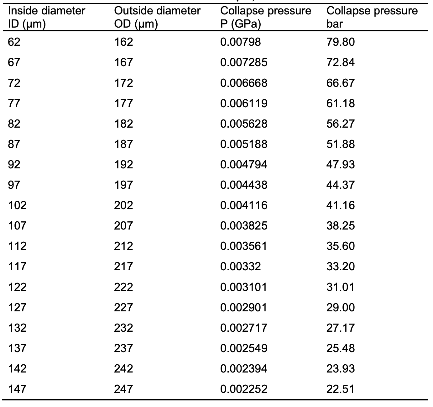
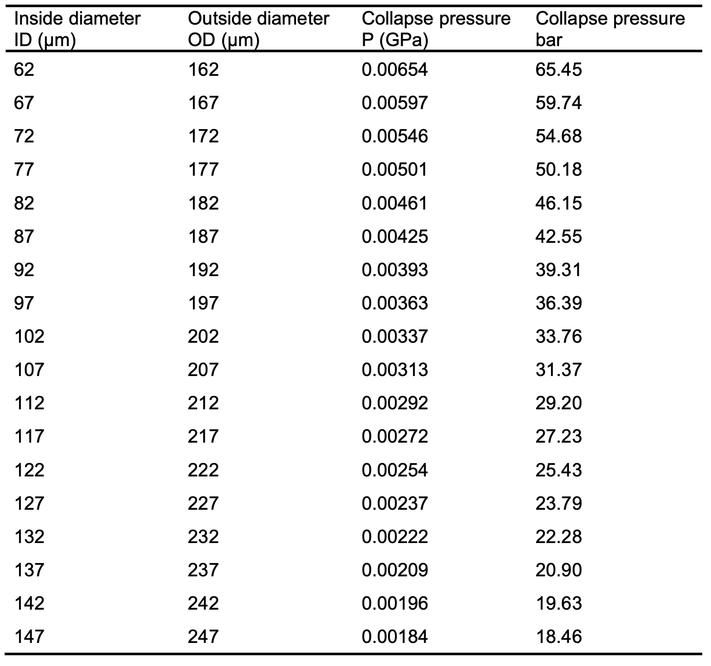
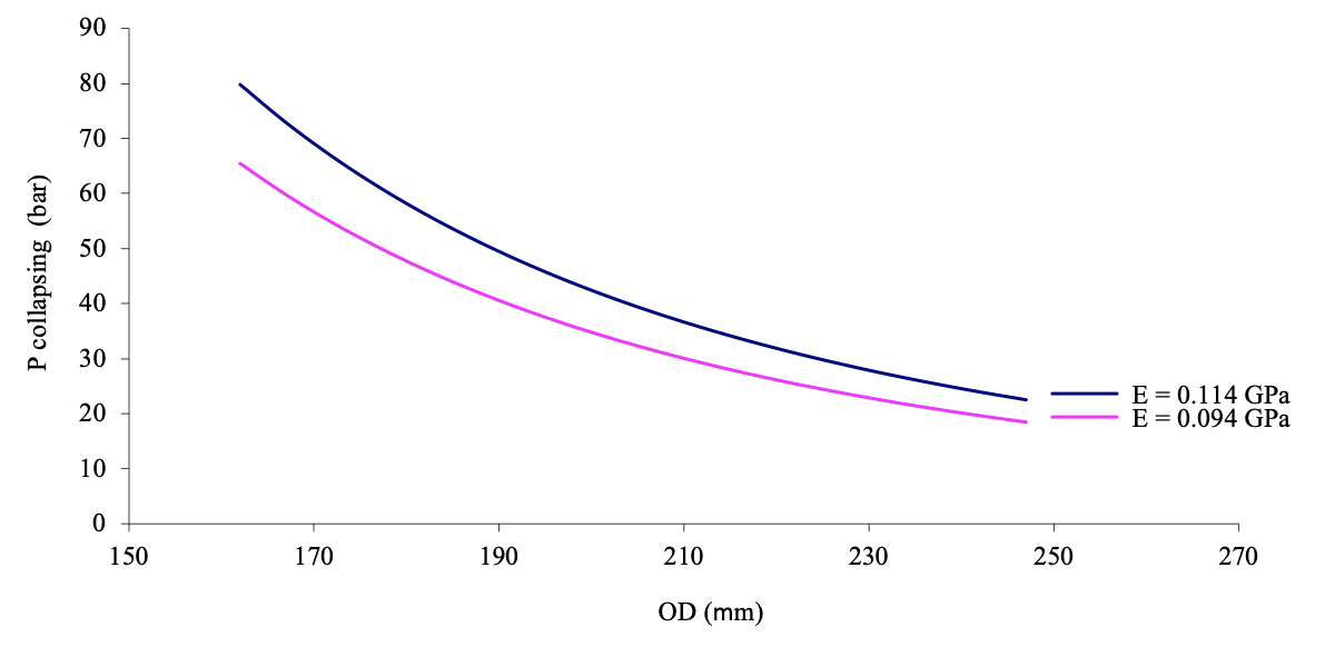
Determining the effect of changing fibre dimensions on the collapse pressure can also be calculated using equation 1 with changing the fibre dimensions of the obtained fibre diameter (237 μm), while maintaining a constant wall thickness. These calculations are presented in Tables 1 and 2, respectively. Figure 2 shows the effect on the collapse pressure of a hollow-fine- fibre, calculated using both values of Young’s modulus (0.114 and 0.094 GPa). Tables 1 and 2 show the influence of varying the outside fibre diameter of 237 μm on the collapse pressure values at two different Young’s modulus values. The variation of outside fibre diameter was done by keeping a constant wall thickness, while increasing and decreasing the inside and outside fibre diameter, respectively, at constant value of 5 μm. The inside diameter was calculated by substituting the value of 237 μm and wall thickness of 50 μm in equation 2 .
The results show that the collapse pressure decreases gradually with increasing outside diameters and decreasing Young’s modulus. Therefore, the collapse pressure is directly dependent on the Young’s modulus and inversely to the outside diameter. From Figure 2, there is a clear indication that the Young’s modulus and the fibre dimensions have a significant effect on the collapse pressure and subsequently give the hollow-fine- fibre enough mechanical strength to withstand high operating pressures encountered in RO without collapse. It can be seen from Figure 2 that there is an acceptable range of fibre dimensions (222 – 247 μm) that showed an ability to withstand the operating pressure for brackish water applications. Typically, the operating pressure used for brackish water desalination would be in the range of 20 – 25 bar as the lower salt concentration creates a lower osmotic pressure and therefore the lower RO pressure is possible. Therefore, a 50 μm wall thickness and outside fibre diameters within the range of 222 – 247 μm would be acceptable for brackish water RO applications.
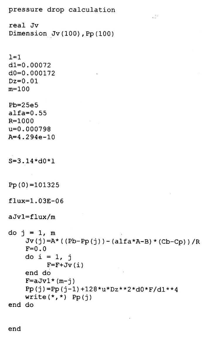
Pressure Drop Across the Wall of a Hollow-fine-fibre Membrane Pressure drop along the fibre bore is greatly affected by the size of internal diameter [11]. Therefore, the pressure drop calculation is necessary for the specified range of the fibre dimensions determined above. The pressure drop along the fibre bore is calculated by the Hagen-Poiseuille equation. Numerical analysis by a computer program (FORTRAN) is used to solve the equation and the software codes are shown in Appendix A . The governing equations in this calculation are fluid pressure drop, material balance and membrane transport equations. The assumptions made in this calculation are as follows:
Fluid Pressure Drop Equations The axial pressure drop inside the fibres is expressed by the Hagen-Poiseuille equation (9):
Differentiating this equation with respect to the length of the fibre, we get (equation 10):
where P is the pressure inside the fibre (Pa), Z is the axial direction of the fibre (m), dI is the inside fibre radius (m), The material balance within the fibre bore is given by the following equation (11):
where dO is the outside radius (m), Jv is the total flux or the solution flux across the membrane (m3/m2 sec) and L is the length of the fibre (m). Differentiation of equation 10 and substitution into equation 11 yields (equation 12):
Equation 12 has the following boundary conditions:
In order to determine the pressure drop along the fibre, the axial direction of the fibre (Z-coordinate) is divided into m = 100 segments each segment is 1 cm in length. Regarding the pressure drop in the fibre bore, however, the axial direction is defined as the length of the fibre. Integrating of equation 12 to obtain the permeate pressure (PPJ) in the fibre segment
Discretisation of equation 13 by changing it to a linear equation yields equation 14 .
This equation will be solved numerically by FORTRAN where Ppj is the pressure inside the fibre (Pa), Membrane Transport Equations The solution-diffusion model is a practical model for explaining membrane permeation, and is described as follows:
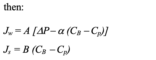
where
where Jw is the water flux through the membrane, Js is the solute flux through the membrane, A is the water permeability constant, B is the solute permeability constant, PB is bulk pressure PP is the permeate pressure,
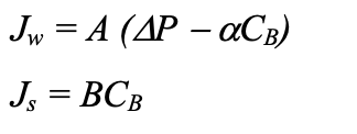
With a tight membrane structure, such as those used for RO desalination processes, a further assumption can be made. The product concentration Cp can be neglected because the flux is so low in these membranes. High-flux membranes have high Cp.
The total flux or solution flux (Jv) in the equations above is given by the sum of the water flux and the solute flux, (Js). With highly selective membranes the solute flux can be also neglected.  In addition, our assumptions will include the use of pure water as feed solution. Thus, the local brine concentration (feed concentration) CB can be neglected, and the solution flux equation becomes (equation 15):
Numerical Analysis to Determine the Pressure Drop The solution flux is calculated according to equation 15, which assumes that permeate pressure (Pp) is equal to atmospheric pressure 101 325 Pa. The bulk pressure PB is assumed to be equal to the feed pressure. For brackish water desalination at lower salt concentration, lower feed pressure, as low as 20 bar, are used. With slightly higher concentration, the high feed pressure of around 25 bar can be used. Equation 15 requires a water permeability constant for CA. This was found in the literature as 4.294 × 10⁻¹⁰ Kg/m2.s.Pa [29]. This water permeability constant is used in the solution-diffusion model and when using pure water is equal to
where D is the diffusion coefficient m2/s , c is the molar concentration kg-mol/m3, v is the molar volume m3/mol, R is the gas constant 8.314 J/mol.K, T is the absolute temperature K, l is the membrane thickness (mm), and the subscript w indicating the solvent (water). According to the Kimura and Sourirajan approach of transport phenomena across RO membranes, the solvent and solute fluxesthrough the membrane are mainly characterized by two phenomena: solvent transport in termsof the pure water permeability constant A, and solute transport in terms of the solute permeability constant B [30]. The solute permeability constant was neglected in this calculation as the feed concentration was assumed to be pure water flux. Therefore, the solution flux for a single hollow-fine- fibre will be calculated as follows :
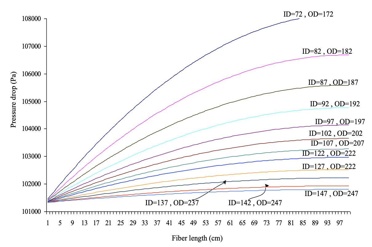
The pressure drop can be obtained using equation 14 , and the finite difference method is applied to numerically solve it. Figure 4 shows the pressure drop across the fibre wall of assumed diameter above for hollow-fine-fibre membranes at wall thickness of 50 μm. Figure 4 shows that the pressure drop along the fibre length decreases significantly as the diameter of the hollow fibre increases. Pressure drop in the fibre bore plays an important role in the productivity of the fibre. The smaller the fibre dimensions, the higher the pressure drop and subsequently lower water flux (less product). Therefore, the workable fibre dimensions should have a smaller pressure drop and also a high collapse pressure resistance within the operating conditions for a brackish water membrane. It can be seen from Figure 4 that, as the fibre diameter increases while maintaining a constant wall thickness, the pressure drop in the fibre bore decreases. The number of fibres that can be accommodated in the module of a given size also decreases. It can be seen from Figure 4 that the range of fibre dimensions of 222 – 247 μm obtained by the collapse pressure calculations have reasonable values of pressure drops compared to smaller fibre dimensions where the pressure drop is high. Hence, the pressure drop calculations will also limit the selection of fibre diameters for brackish water desalination. Therefore, the range of 222 – 247 μm would be acceptable for making CA hollow-fine-fibre membrane for brackish water desalination in terms of collapse pressure and pressure drop.
Conclusion The relationships between the collapse pressure and pressure drop calculations were considered in order to determine an acceptable range of fibre dimensions capable to withstand brackish water operating conditions of 20 – 25 bar with smaller pressure drop. The collapse pressure calculations showed that outside diameters and membrane wall thickness play an important role in determining the membrane operating pressures. A fibre dimensions in the range of 222 – 247 μm showed good resistance against collapse of brackish water operating conditions. The hollow-fine- fibres with range obtained above (222 – 247 μm) also showed a lower pressure drop within the brackish water operating conditions during the calculations. Thus, the hollow-fine-fibre membranes in the range of (222 – 247 μm) showed high resistance to withstand the brackish water operating conditions at relatively low ratio of wall thickness 50 μm to outside diameter and thereby provide an advantageously large bore. diameter to minimize the pressure drop to permeate passing within the bore. References
|
|||||||||||||||||||||||||||||||||||||||||||||
